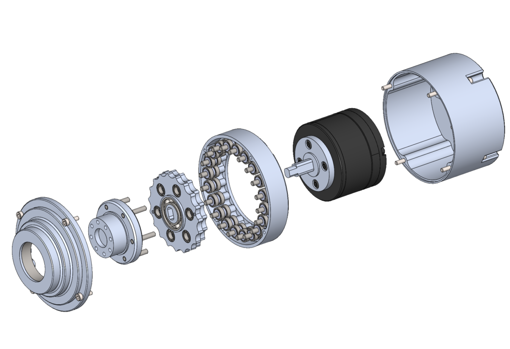
A cycloidal drive is one of the well known speed reducer which give none backlash, and mostly are used for robot manipulator. From my opinion, this gear drive is very attractive in both performance and manufacturing processes. Unlike harmonic drive that requires a flex spline or flexible part, cycloidal drive requires only rigid part, this makes the manufacturing a lot easier. If you have 3D printer at home you can easily make it from your home, or if you have CNC machine, you can even make a stronger part and there is no need of any special machine.
Design tips
There are many open source complete parts that you can download and use it right away. But the thing is if the ratio or the standard parts like pin, bearing, or motor that come with doesn’t match on what you have or need, then it’s hard to modify, because some slightly changes may affect on the other components, and finally it may not be able to assemble anymore…
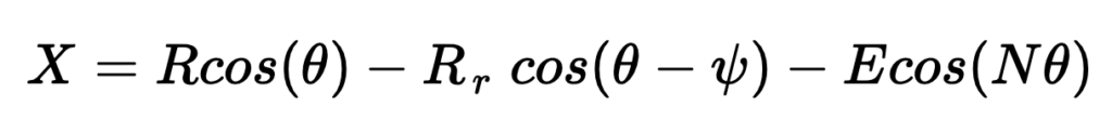
So I would like to share some design tips and reference that you can follow along, then whatever the ratio and standard parts you want/have, you can make it too. The most difficult part to design is the cycloidal disc. To design the disc, there is an equation which described about this
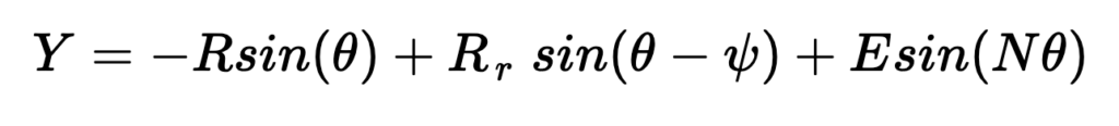
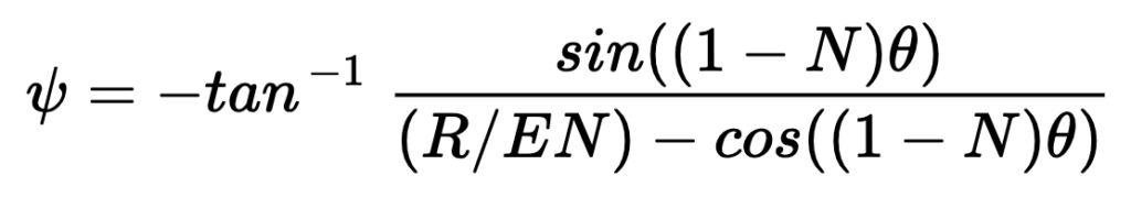
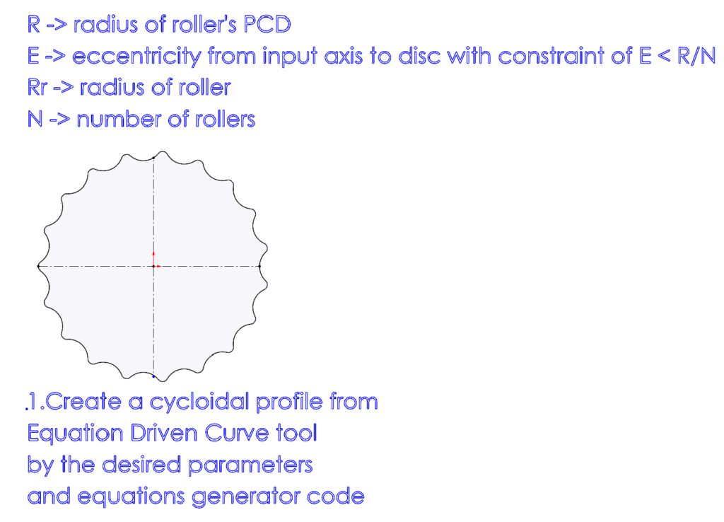
X and Y are parametric equations which has the parameters definition listed below
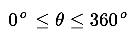
If we know roughly what is gear ratio (N) we want to use, how big of our drive unit is going to be (R, Rr, E), then we can bring those number into the X,Y equations and plot the curve by varying θ from 0 to 360.
If you are using Solidworks, there is a tool “Equation Drive Curve” which you can input these two equations and the variable angle θ then it would generate the corresponding curve for us.
I have made up a simple python code, which is going to generate two equations form then we can just copy and paste these equations into Equation Drive Curve tool of Solidworks. Please check out the code here.
The parameters you chose should make sense in term of size and it should be reasonable, otherwise you will get a really strange curve or it might not even generate any curve for you.
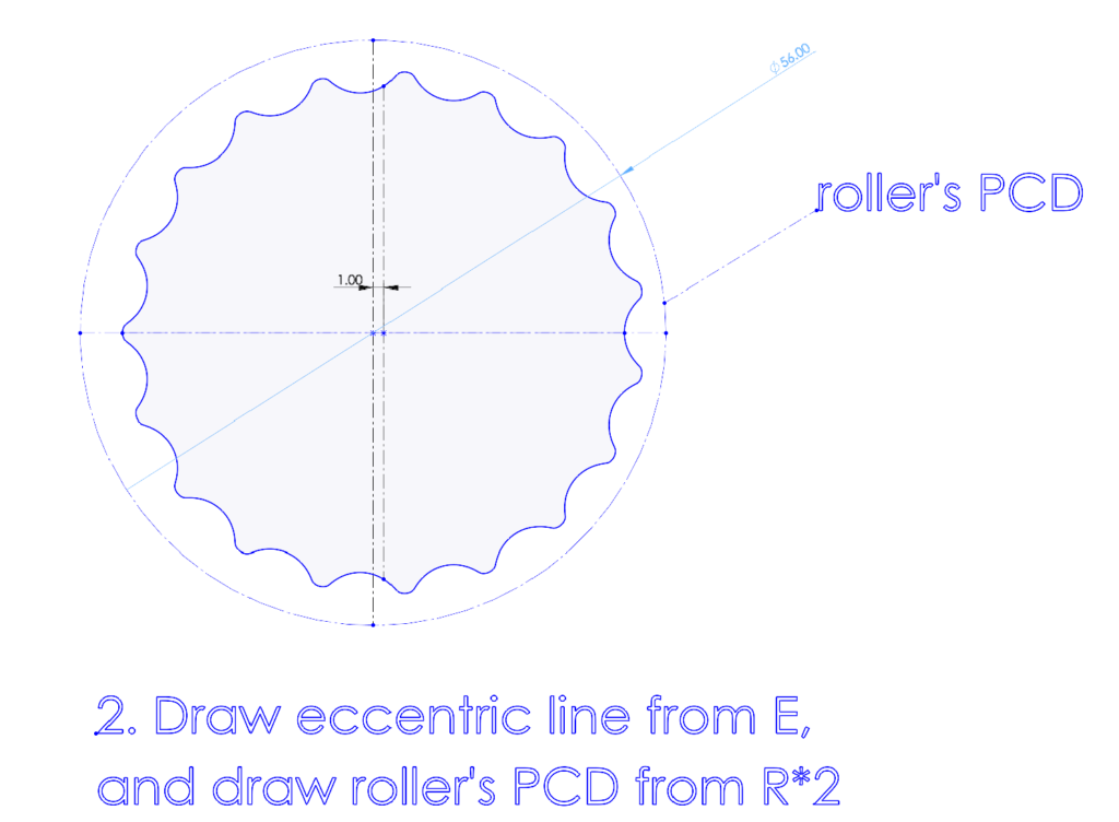
After you got a nice curve of cycloidal profile, create a center line with an eccentricity as E that you chose and draw the roller circle from that center point. This circle has the same radius as R that you chose.
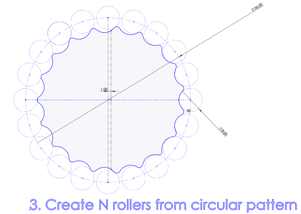
Draw a roller circle which has a radius of Rr, then make a circular pattern of the roller on the previous circle. The number of roller is as N. Please make sure to select the correct center point, it should be the center of P.C.D. not the center of cycloidal profile. You will notice that all the rollers are touching the profile perfectly without intersection or interference. If not, you might do something wrong on the dimension or circular pattern.
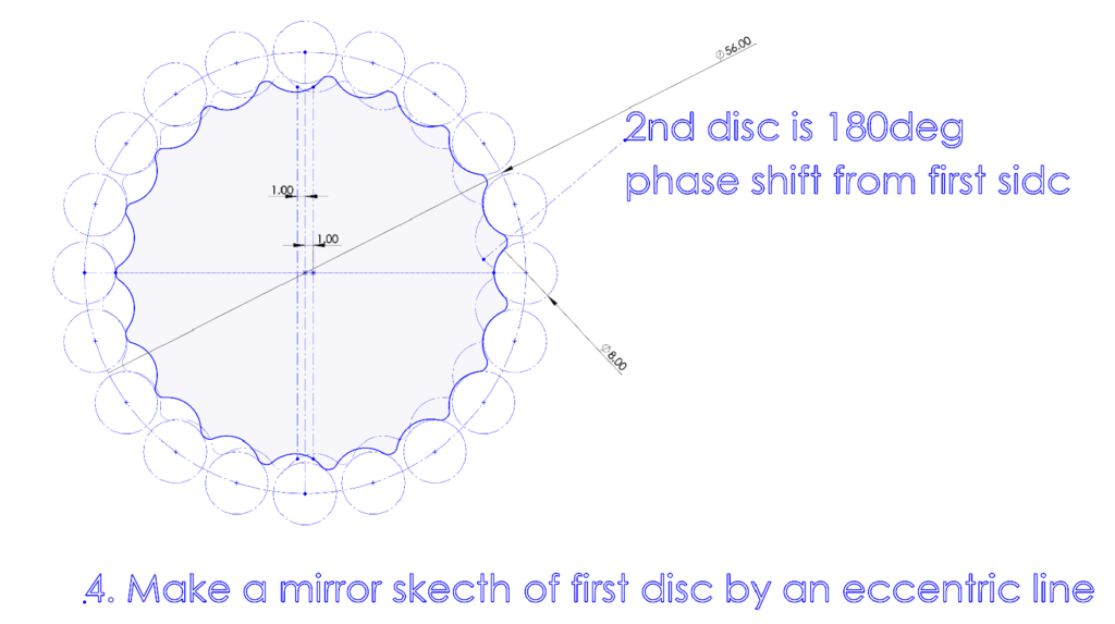
Try create another disc by mirroring from the center line. The second disc should perfectly touch the disc as well. This second disc with 180degree phase shift can reduce vibration which from the eccentric cam.
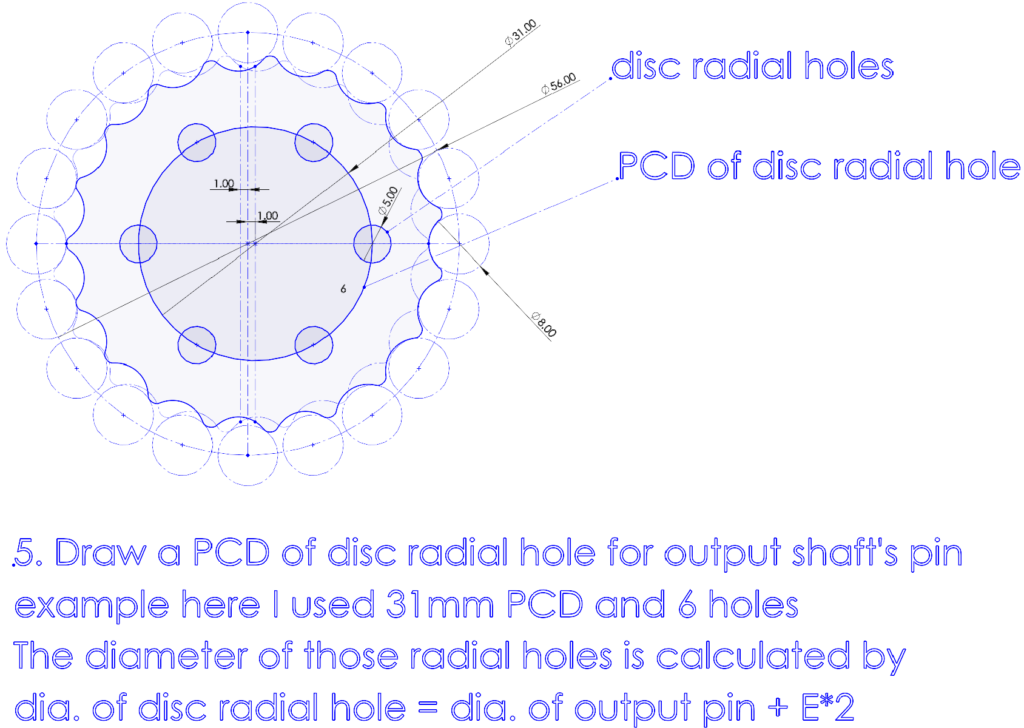
Next is the pin hole on the discs. First calculate the diameter of pin hole by the equation written in the image, you can choose any size of P.C.D. that would fit on your disc.
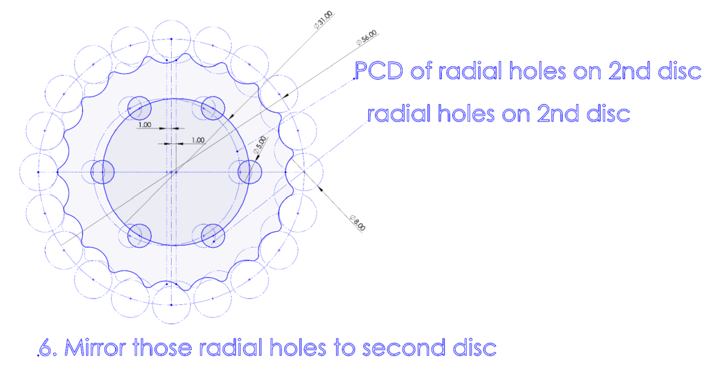
Mirror those pin holes and P.C.D. from center line for a second disc.
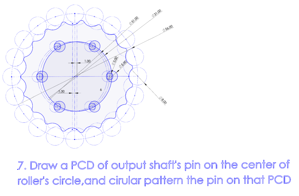
Draw the output pin between two holes from two discs, you will see that the pin will touch perfectly on these circles. Then finally just circular pattern on this pin.
After you have finished planning all the sketches, it’s time to draw each part separately, extrude, and assemble it! If you follow along the guide you’ve made, I believe the final design should be perfectly fit. So in case you want to make it from 3D printer, I suggest to adjust the profile a little bit smaller, otherwise it would be too tight on real assembly.